Home ← Services ← Engineering Research Center ← Engineering and topographic-geodetic surveys
Home ← Services ← Engineering Research Center ← Engineering and topographic-geodetic surveys
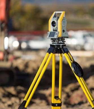

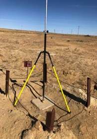

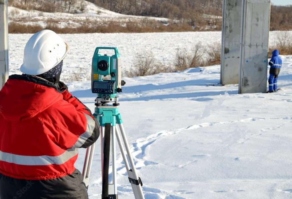
A survey geodetic network is created in order to develop horizontal and vertical control to a density that ensures the creation of engineering and topographic plans in the process of topographic survey at a scale of 1:5000 – 1:200.
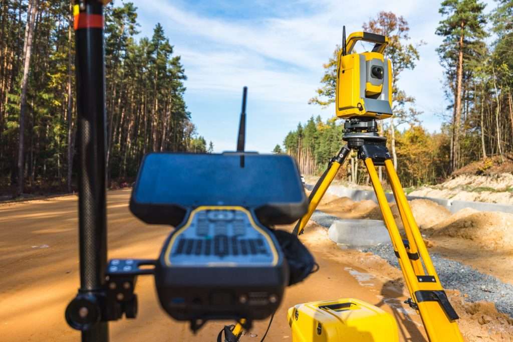
A survey (horizontal and vertical) geodetic network is developed using satellite technologies, the construction of theodolite traverses, the development of triangulation, linear-angular networks, direct, reverse and combined serifs and their combination, technical leveling traverses, as well as satellite high-altitude determinations.


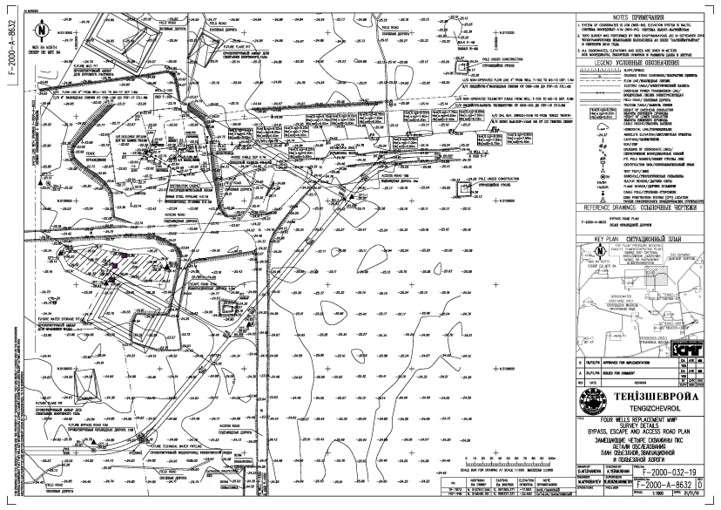
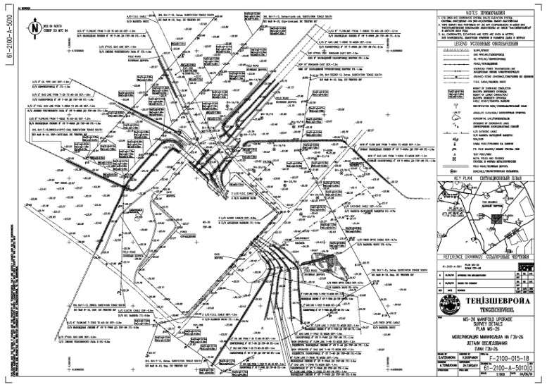
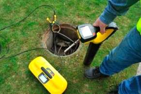
Our company has extensive experience in various types of geodetic surveys, including executive surveys of underground communications. Topographic survey is conducted using modern instruments by highly qualified specialists. It is carried out during the construction of engineering communications before the trenches and pits are filled. Determining the location afterward would be extremely challenging. During the survey, all types of underground installations must be captured: turning angles, inspection hatches, chambers, all locations of changes in pipe slopes, their diameter, places of branching and connections, etc. Each type of engineering communication has a specific set of objects that are mandatory for surveying.
Linear structures, together with certain technological devices designed for transporting various liquids and gases, as well as transmitting energy, are considered engineering communications. Traditionally, they are divided into two groups: aboveground and underground communications. Their complexes are also called engineering networks, and existing individual communications are also referred to as routes or installations.
If the land plot previously had laid engineering communications, but construction or reconstruction of an old building is planned on it, some installations may be exposed by new trenches. Any changes that will occur in the subsequent period must be captured and documented. An important aspect is the planned identification of underground communications. For built-up areas, the starting position is taken from solid points of capital construction or from points of the reference geodetic network. For undeveloped areas, it starts from equipment points for executive survey or also from points of the reference geodetic network.

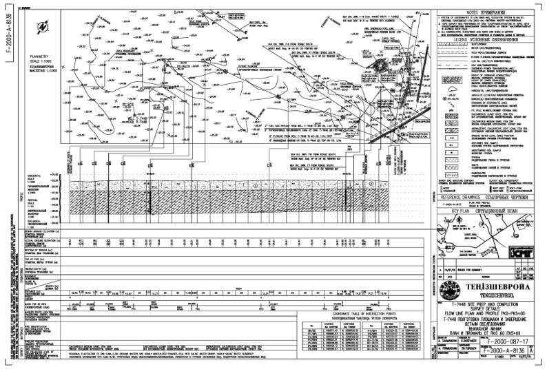
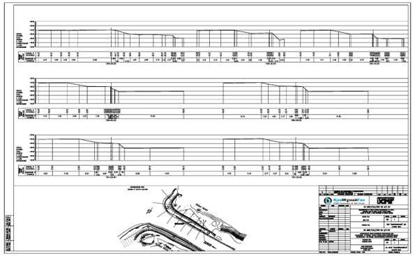
Field routing is a transfer of designed route to the terrain specifying its changes and fixing out. The route shall be identified on the ground by position of its main points:
1) tangent points of the curve (TP)
2) top angles of curvature (TA)
3) middle of the curve (MC)
4) points of crossings with axes of structures
These points on the ground are fixed with signs. The type of sign depends on the required period of their preservation on the ground. Leading points are fixed with landmarks. Transfer of the route from the map to the terrain is carried out either according to the coordinates of its main points, or according to the data linking the route to terrain objects. The coordinates of points and anchor elements are determined graphically on the map. Therefore, the accuracy of transferring the main points to the terrain is mainly determined by the scale of the map. After transferring the route points to the terrain, theodolite or polygonometric passages are laid, which include all the points mentioned. During these works, between the curvature angles, “hanging” and measuring lines are carried out, horizontal angles are measured, and stationing are laid out with marks of plus points and diameters. When laying out the stationing, the lines are measured with a measuring tape (line) in one direction, comparing the values with cross-wire meter. Pickets are fixed with wooden stakes. A “guard stake” is set up nearby and a trench is made. The route beginning is designated PK0. A number of the next stationing means the number of hundreds of meters of the route from its beginning. Characteristically, a relief point is marked with plus points, which indicate the distances to the nearest pickets, for example:
PC5+68.
When placing pickets on sloping sites, corrections for the slope are introduced into the measured distances.
Laying out near the curvature angles has its own specifics.
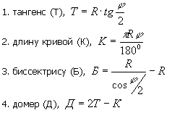
The main elements of the curve:
TP = TA — Т TA = TP + К MC = TP + К/2
Control:
TP = TA-D + T, SK = TP – K /2
Under the deformations of buildings and structures we understand the change in the spatial position of the points of the structure, its parts or the entire structure as a whole. These changes occur in time under the action of external and internal forces.
Buildings and structures on soil foundations can move in a horizontal plane, which is called shear, or move vertically. Such displacements directed vertically upwards are called uplifts, and downwards – precipitation. In addition, as a result of unevenly flowing precipitation along the perimeter of the structure, its main planes can slope.
Such slopes are called rolls.
Uneven settlements occur primarily as a result of different pressures of parts of the structure and unequal compressibility of the soil under the foundation, which, in turn, causes various kinds of displacements and deformations in the structure structures.
The results of practical field observations of precipitations and uplifts of structures are one of the main materials characterizing the foundation bed stability and the foundation reliability. Carrying out high-quality high-precision measurements of spatial displacements of structures makes it possible to obtain reliable information about such important parameters as the depth of the compressible thickness of the foundation soil and the attenuation of settlements over time, to establish a practically limit for uneven settlements, after which strength is impaired and dangerous rolls, distortions, cracks appear. Finally, the results of studies of precipitation and uplift of structures are a good basis for the development of certain empirical methods and techniques for fast and reliable settlement prediction.
Systematic instrumental measurements of precipitations and deformations of structures are of great practical and scientific importance.
The practical significance lies in the fact that the measurement results are used as source material to characterize the stability of the foundations and the entire structure as a whole, allow to plan in advance measures to eliminate the causes of deformations, carry out repairs, etc.
•Preparation of terms of reference
•Obtaining optimal technical conditions for connecting the facility to utility system
•Obtaining an Architectural and Planning assignment in the Department of Architecture and Urban Development
•Carrying out of public hearings
•Approval of motor road projects with the Policy Department
•Approval of projects in Water resources inspection
•Approval of design solutions in the Department of Industrial Safety
•Development and expertise of Declarations of industrial safety with obtainment of registration numbers
•Carrying out of Energy expertise
•Preparation of traffic diagram with indication of material delivery points.
•Approval of a Plot plan with the Chief Architect
• Analysis of detailed documentation for compliance with standards in the field of architecture and construction, environmental protection and sanitary-epidemiological welfare
•Uploading of design documentation to the web-portal of Comprehensive extradepartmental expertise
•Work with experts, solving the arising issues, approval of technical and economic indicators
•Obtaining a positive expertise conclusion
•Obtaining an environmental emission permit
•Obtaining a coupon for commencement of construction and assembly works.